DFACS - LISA Pathfinder

Drag Free and Attitude Control System (DFACS)
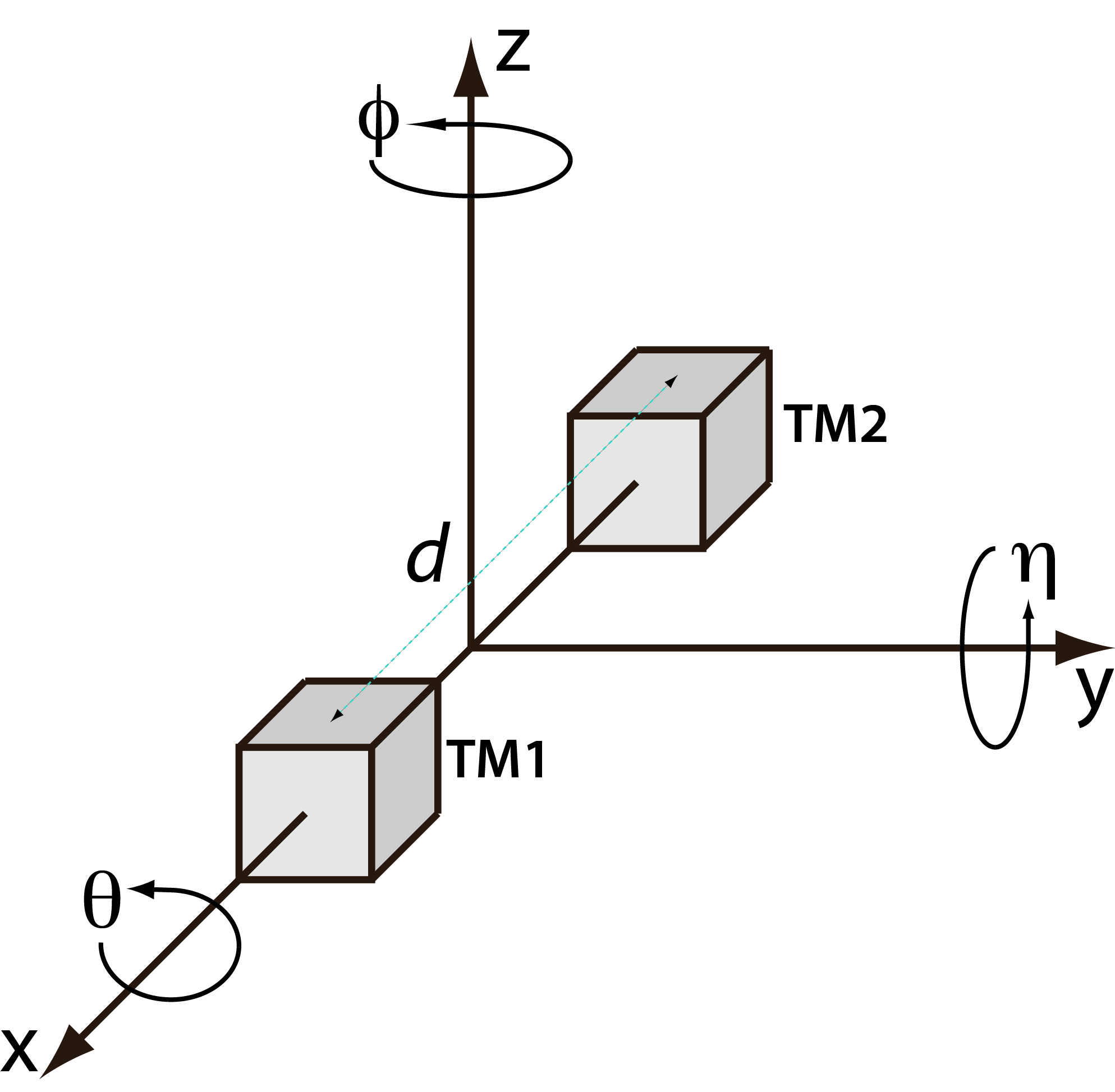
The Drag-Free Attitude Control System (DFACS) is probably the single most important subsystem on board. The main objective of the DFACS is to control the spacecraft dynamics in such a way that the main requirement on the residual acceleration. Like any control system, DFACS makes use of sensors and actuators. The spacecraft attitude is sensed by means of a pair of star trackers with a measurement error of 32arcsec/√Hz. With reference to the figure below, the test masses position (xi, yi, zi with i=1,2) and attitude (θi, ηi, ϕi with i=1,2) with respect to their housing inside the inertial sensor, are sensed through two different means:
- electrostatic readout based on capacitance electronic measurement, with a measurement noise of 1.8nm/√Hz for x, y, z and 200nrad/√Hz for θ, η, ϕ over the measurement bandwidth.
- optical readout based on laser interferometric measurement, with a noise of 9pm/√Hz for x1 and x2-x1 and 20nrad/√Hz for η1, ϕ1 , η2, ϕ2 over the measurement bandwidth.
The actuation on the spacecraft attitude is performed by the set of micropropulsion thrusters, described later in this section, with a noise of 0.1μN/√Hz. The forces and torques on the test masses are provided by the inertial sensor electrostatic actuation. During the science modes, the maximum differential acceleration noise allowed on the TM's is 10-14ms-2/√Hz.
The DFACS task is to control the 15 degrees of freedom (DOF) present on-board (6 DOF per test mass and 3 DOF for the attitude of the spacecraft) to fulfil the following objectives:
- to shield one test mass - the drag-free test mass - from external disturbances along the sensitive x-axis over the measurement bandwidth [1 mHz to 30 mHz]. The spacecraft is therefore controlled to follow the drag-free test mass, which is free to float in its housing, only subject to the forces that directly impact on the test mass (e.g. thermal radiation pressure, magnetic field interaction with TM), called internal forces fi and to the non contact coupling with the electrodes housing (e.g. due to electrostatic field and gravity gradient), called parasitic stiffness, ω2i.
- to measure by laser interferometer the differential acceleration between the drag-free test mass and the second test mass maintained centred in its housing using electrostatic capacitive forces.
- to keep the spacecraft pointed to the sun and the fixed communication antenna pointed to Earth.
This is realised by careful selection of the drag-free degrees of freedom and frequency band separation. The drag-free DOF conditions are not belonging to one TM, but on 6 DOF's of the two TM's: x1, y1, z1, θ1, y2, z2. Below the measurement bandwidth the test masses drag-free DOFs, θ1, y1-y2, z1-z2, are controlled using capacitive suspension control in order to maintain the attitude of the spacecraft according to the star tracker measurements and attitude guidance law (this table lists the control degrees of freedom). Above the measurement bandwidth, the spacecraft is controlled by means of the microproplusion system.
The DFACS has several modes of operation which are used during the on station operations after release of the TM from the caging mechanism. One particular science mode, Science Mode 1, is particularly interesting for the characterisation of the spurious acceleration noise acting on the TM's. In this mode, the distance between the two TM's, measured by the interferometer, is used by the controller as the main signal to control the position of the spacecraft and of the suspended test mass. Neglecting the thermoelastic deformation of the inertial sensors and optical bench and the cross-talk terms, the interferometer readout measurement equation is shown below:
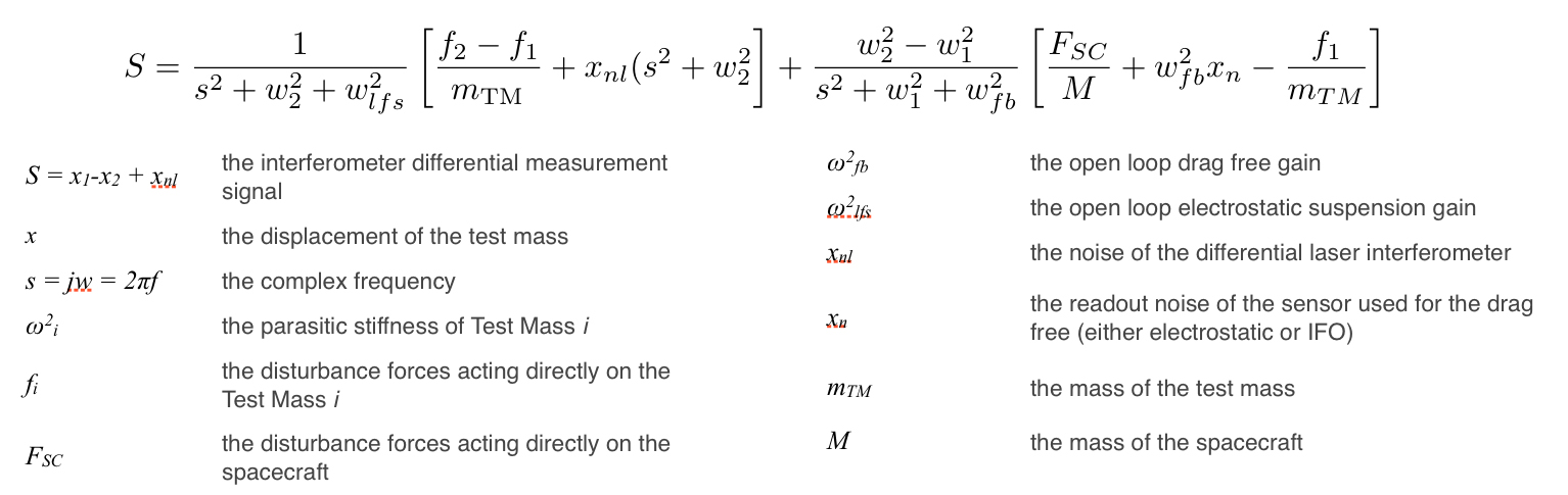
From the equation, we can observe that there are three main contributions to the measured signal, which should be as low as possible, as it is directly related to the residual differential acceleration. The first is a combination of the direct internal forces acting on the test masses, the second is a term proportional to the differential interferometer noise and the third is the so-called spacecraft jitter noise, the physical movement of the TM along the measurement axis. It is instructive to examine these terms one by one.
The first term, the internal forces contribution, enters into the equation without multiplying factor, so it cannot be minimised, with respect to other contributors, by tuning system parameters. This means that the term has to be minimised by design and by proper selection of TM material and inertial sensor construction. The multiplying term can be used to reduce the effect of all the contributions, however at a given frequency band, one can only tune the gain of the electrostatic suspension ω2lfs, which cannot be increased indefinitely. In other words, if the internal forces term is too large by LTP and system construction, it cannot be mitigated by system tuning. The second term is due to the interferometer noise. This is more important at high frequencies and at large ω22. However the intrinsic noise of the interferometer is rather small. The third contribution is dominated by the disturbance forces on the spacecraft (e.g. solar pressure fluctuations and micropropulsion force noise) and by the noise of the measurement system used for the drag free control. In the case where the interferometer is used, the term xn is small and the only remaining term is FSC. This term can be minimised by tuning two system parameters: the difference between the parasitic stiffness ω22-ω21 and the drag free gain ω2fb. The first term must be minimised, while the second maximised.
The above illustrates the basis upon which the on-board calibration and scientific runs will be performed and how the system will be tuned for optimal performance.