Inertial Sensor - LISA Pathfinder

Inertial Sensor Subsystem
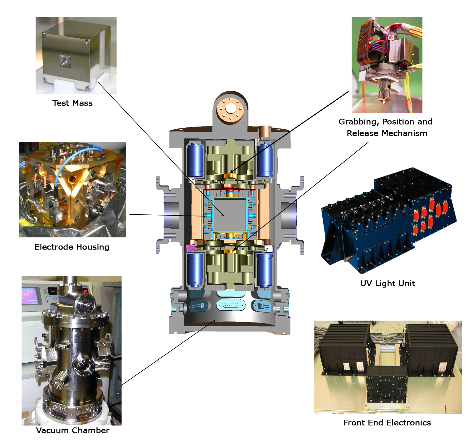
The inertial sensor subsystem consists of the test masses and all systems interacting directly with the test masses, i.e. the electrode housing, front-end electronics, vacuum system, charge management, and caging mechanism. Each will be described in turn.
In LISA Pathfinder, the test masses consist of a 1.96kg cube of Gold:Platinum mono-phasic alloy of dimension 46mm on a side. The alloy is formed from 73% gold and 27% platinum, chosen as this material can have an extremely low magnetic susceptibility (χm ~10-5) and high density ~20kgm-3. The combination of both greatly reduces the effect of external forces on the test mass.
The position of the test masses is readout by two means: high resolution laser interferometry, and electrostatic (capacitive) sensing. The former only senses the test mass position along the sensitive axis (the line joining the two test masses) and the angles of rotation around the axes perpendicular to the sensitive axis, whereas the capacitive sensor measures the position of the test mass in all six degrees of freedom. The capacitive sensor comprises a hollow cubic molybdenum housing with isolated gold coated molybdenum electrodes mounted in the faces (see Figure). The housing is sized to allow for a 4mm gap between the electrode faces and the test mass. The size of the gap is a trade off between reducing the effects of noise sources, e.g. from uncontrolled potentials on the electrodes, and being able to meet the capacitive sensing requirement of 2nm/√Hz over the measurement bandwidth.
The capacitive readout system, known as the Inertial Sensor Subsystem Front-End Electronics (ISS FEE), is arranged such that electrodes facing opposing faces of the test mass are combined via a capacitive bridge. A change in the position of the test mass gives a differential, bi-polar, signal. As well as sensing the position of the test masses, the ISS FEE can also be used to actuate (force) the test mass. In the basic operational mode of LISA Pathfinder, one test mass can be considered drag free, i.e. the position of this test mass with respect to the spacecraft is fed back to the thrusters such that the spacecraft is forced to follow the test mass. However, in this case, any unbalanced external force acting on the second test mass will cause a differential motion between the drag-free mass and the second test mass, which, if uncontrolled, will lead to a collision with the electrode housing after a period of time. For this reason, the ISS FEE must force the second test mass back to the optimum location within the electrode housing. However, this feedback loop primarily acts at frequencies below the measurement bandwidth, in order not to add noise at the frequencies of interest.
The test mass and electrode housing are mounted inside a dedicated vacuum enclosure. In order to meet the instrument requirements, the vacuum around the test mass must be maintained, throughout the mission lifetime, to less than 10-5Pa. While inter-planetary space is an exceptionally good vacuum environment, the space inside, a spacecraft is considerably more dirty (due to outgassing) than can be tolerated by the LISA Pathfinder inertial sensor, hence the need for a dedicated vacuum chamber. As with all equipment used in LISA Pathfinder, only non-magnetic materials can be used in the system, forcing the vacuum chamber to be manufactured from titanium as opposed to the standard stainless steel construction techniques. Also, in order to limit the pressure increase due to outgassing or virtual leaks within the vacuum enclosure, the system will be vented to space via a dedicated venting valve mounted to the lower flange of the vacuum enclosure.
As there is no physical contact between the test mass and the surrounding environment, one issue that must be dealt with is charging of the test mass due to cosmic ray and solar energetic particle impacts. A build up of charge on the test mass, coupled with the potentials on the electrodes, will lead to additional noise in the test mass position. The actual charge on the test mass is measured by commanding the test mass to rotate with a given amplitude and looking at the corresponding actual displacement of the mass. The difference between the commanded and actual motion provides a measure of the test mass charge. The charge is then controlled using a non-contact discharge system based on the photo-electric effect. UV light from Mercury vapour lamps is channelled to the electrode housing via fibre optic cables. Depending on the sign of the charge on the test mass, the light is either shone onto the test mass or the electrode housing. The system has two modes of operation: rapid discharge, were the science run is stopped, the charge measured, and the UV lamps set to near maximum intensity to discharge the mass in as quick a time as possible; and a continuous discharge mode, where the science measurement is not interrupted, the mass is forced to rotate around the x-axis and the UV lamps are set to a low intensity such that the charging rate is balanced, preventing charge build-up on the mass.
A further challenge which is unique to space flight hardware is the need for a launch-lock device to prevent hardware being damaged during the extreme vibration conditions experienced at launch. In LISA Pathfinder, this is especially true for the test masses - the most sensitive part of the experiment must survive a random load of ~50grms, requiring a holding force of ~1200N, while not damaging the gold coated surface of the cube. In addition to the launch load requirement, when on-orbit, the device must release the test mass within an error box of 200μm, with a velocity of less than 5x10⁻⁶ms-1.
These requirements are met by the Caging Mechanism Assembly. This device consists of three actuators: a first stage single-shot actuator to provide the 1200N preload; a second stage positioning actuator, which is used to break the adhesion of the launch lock, and position the test mass to the desired location; and finally, the release actuator, a small diameter pin which is used to break the adhesion of the positioning plunger, and release the mass with the required accuracy.
Several other challenges must also be solved in order to meet the requirements of the LTP. These include: balancing of the differential gravitational force and gradient at the test mass positions - achieved by mounting compensation masses inside, and external to, the vacuum enclosure; creating a thermally quiet environment around the test mass - a temperature stability of 10-5K/√Hz over the measurement bandwidth is required; associated with the thermal stability requirement is the need to have thermometers with a resolution better than 10-5K/√Hz; and as mentioned earlier, no magnetic materials can be used - this makes the design of several of the subsystem units especially difficult (e.g. vacuum chamber, mounting brackets, bolts, etc)