Optical Metrology Subsystem - LISA Pathfinder

Optical Metrology Subsystem
The Optical Metrology Subsystem (OMS) is the high resolution laser interferometric readout of the test masses' positions. The OMS comprises several subsystems, namely; the reference laser unit, the laser modulator, optical bench interferometer and the phase meter (see figure).
The Reference Laser Unit (RLU) employed on LISA Pathfinder is a 35mW Nd:YAG non-planar ring oscillator of the same design commonly used in metrology labs around the world. This laser design is ideal for space applications due to its small size, high electrical to optical efficiency and inherent low noise operation. The challenges for space applications come from the need for a robust design which can survive both the launch loads and thermal environment, as well as having a sufficient lifetime to guarantee the life of the mission. All of these challenges have been overcome and similar lasers are now flying in space on optical communication satellites. The RLU output is fibre coupled using single-mode, polarisation-maintaining fibre. The fibre couples the light to the subsequent component in the optical chain, the Laser Modulator (LM). The LM consists of a beam splitter, two acousto-optic modulators, and optical pathlength actuators. The light from the laser is split into two paths, each path is passed through an acousto-optic modulator (also known as a frequency shifter). One modulator is driven at 80MHz, while the other is driven at 80MHz+~1kHz, thereby creating two beams with a frequency difference of ~1kHz: the heterodyne frequency of the interferometers. The beams are then passed through the optical pathlength difference (OPD) actuators. The OPD is used to stabilise the fibre optic paths leading to the optical bench. After the OPD, the beams are transmitted, again via single mode/polarisation maintaining (sm/pm) to the Optical Bench Interferometer (OBI).
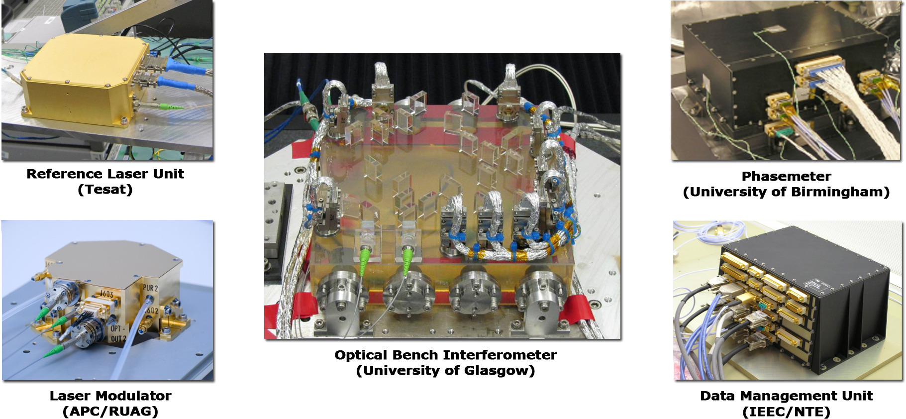
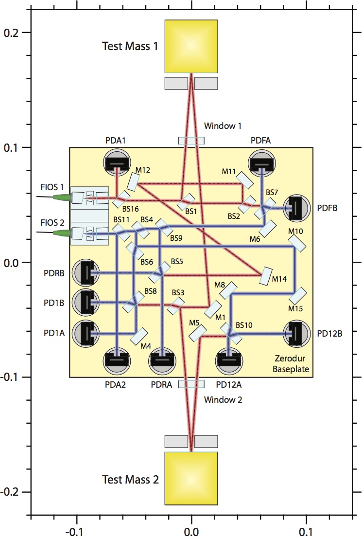
The main function of the OBI is to direct the beams to the relevant positions in 3-dimensional space, without adding any significant noise to the measurement path. The primary optical bench requirement can be stated that the pathlength noise induced by the components on the optics bench should not exceed 1pm/√Hz over the measurement bandwidth. The optical bench is constructed from a block of Zerodur ceramic glass measuring 200 x 212 x 22.5mm. Fused silica mirrors and beamsplitters are used to reflect the two beams to form four interferometers on the bench: the x2-x1 interferometer which measures the differential motion of the two test masses - this is the primary science measurement of the mission; x1 interferometer which measures the position and angles of test mass one with respect to the optical bench (and therefore, the spacecraft); the Frequency interferometer which is an unequal arm Mach-Zehnder interferometer, sensitive to laser frequency fluctuations - the output of this interferometer is used to stabilise the laser frequency; and the Reference interferometer which is a rigid equal arm interferometer which provides the system noise floor, and is used to stabilise the fibre pathlengths via the OPD. The light from each fibre is also sent directly to a photodiode which is used to monitor the laser intensity noise. The signal from these photodiodes is used to stabilise the intensity of both beams by feeding back to the acousto-optic modulator drive signal. The figure below shows the optical layout of the optical bench.
The signals from the photodiodes of each interferometer (each interferometer has two quadrant photodiodes for redundancy) are sent to the Phasemeter Assembly. The phasemeter samples the data at 100Hz and performs a Single Bin Discrete Fourier Transform to measure the phase of the signals at the heterodyne frequency. This technique is used due to the efficiency of the algorithm. The phasemeter not only outputs the longitudinal phase from the respective interferometers, but also outputs the angles between the wavefronts interfering on the photodetectors - commonly known as differential wavefront sensing (DWS). The latter signals from the x1 and x2-x1 interferometers are used to align the test mass to the interferometer. The longitudinal signals from the interferometers are used to stabilise the laser frequency, the optical pathlength, and (with the DWS signals) as inputs for the DFACS.
As mentioned above, the phasemeter samples the data at 100Hz. However, the 100Hz samples are not required for routine operation, and so the data is downsampled to 10Hz prior to transmission to the on-board computer (and hence the DFACS). The downsampling is performed inside the Data Management Unit (DMU) - a 12MHz ERC32 processor. The DMU is also responsible for the interface to the LTP subsystems, routing telecommands and timing information to the units, and collecting and transmitting telemetry to the on-board computer. The DMU also controls the diagnostic subsystems, consisting of heaters/ thermometers, coils/magnetometers, and a radiation monitor. The diagnostic items are required to isolate particular noise sources in the LTP.