RCS - Ulysses
Attitude and Orbit Control Subsystem
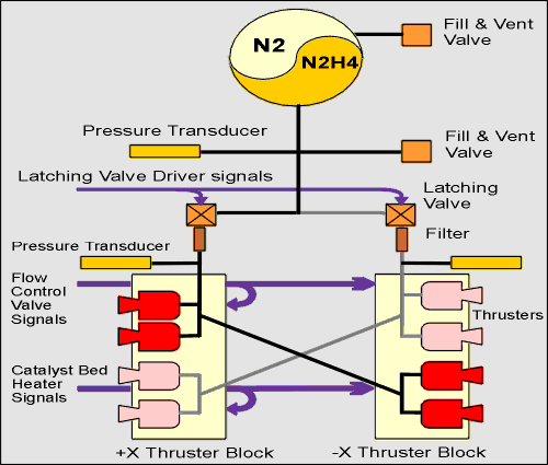
Reaction Control Subsystem
This diagram shows more detail of spacecraft Reaction Control Subsystem (RCS). Click on an area of this image to obtain a more detailed description of the units of interest.
The RCS provides for the storage of spacecraft propellant, eight rocket motors, and the pipes and valves necessary to regulate propellant flow from the tank to the correct thrusters. The subsystem also has pressure transducers and temperature sensors that provide telemetry to the Data Handling Subsystem.
The tank is a titanium alloy shell containing anhydrous monopropellant hydrazine and nitrogen pressurant separated by a membrane. The total volume of the tank is 44.66 litres, and was designed for a load of 33 kg of hydrazine pressurized to 22 bar at 20 °C at launch.
The actual values after the hydrazine was loaded into the tank at the launchpad were:
- fuel mass - 33.49 kg
- tank temperature - 24.3 °C
- tank pressure - 22.8 bar
The latest (mid-January 2004) values are:
- fuel mass - 7.93 kg
- tank temperature - 10.6 °C
- tank pressure - 7.3 bar
Latching Valves
The tank is connected to the two thruster blocks (Thruster Block 1 and Thruster Block 2) via two Latching Valves, to enable either section to be isolated during operations, or in the event of a leak developing in one of the pipe branches. Each valve can latch in the 'open' or 'closed' position. The latching valves can also allow backflow of fuel from the branches into the tank when in the 'closed' position; this is order to prevent excessive pressure buildup in the pipe sections.
Thermal Constraints of the Reaction Control Subsystem
Fuel-bearing components are specified to be kept above 5°C. This is to prevent the fuel, hydrazine, from freezing, which would cause two problems. Firstly, the fuel would not flow to the thrusters and no manoeuvres would be possible. Secondly, if the fuel were to subsequently thaw, pockets of expanding liquid could form possibly rupturing RCS sections.
During the prime mission (1990-1995), meeting this requirement was not difficult, but with RTG power levels becoming so low it is no longer possible to keep remote RCS components above (5+margin)°C, particularly when the margins have been made particularly generous. In order to keep as much of the payload operating as safely possible, it is necessary to trim thermal margins to the lowest level. This in turn necessitates careful calibration of the spacecraft Thermal Model against in-flight temperature data.
The Reaction Control Subsystem (RCS) has several thermistors that measure component temperatures directly, shown on the right. There are also thermistors elsewhere on the spacecraft that can be used to infer RCS component temperatures.
Early in the mission, the available telemetry and generous thermal margins were sufficient to ensure compliance, however with steadily decreasing power availability, greater scrutiny of margins and more insight on the thermal behavior of all RCS components was necessary.
|
- Removed a total of (1) style float:left;
- Removed a total of (2) align=center.
- Removed a total of (2) align=left.
- Removed a total of (2) border attribute.
- Removed a total of (1) cellpadding attribute.
- Removed a total of (1) cellspacing attribute.
























 Sign in
 Science & Technology