EnVision Definitions - EnVision
General
| Item | Definitiond / Description |
|---|---|
| Accuracy |
The closeness of agreement between a measurement and the accepted reference value. The term accuracy, when applied to a set of measurements, involves a combination of random components and a common systematic error or bias component, and can be expressed as follows:
Based on ISO standard 3534-1 (ISO, 1993), and ISO/EC Guide 98-3:2008 – Section 4.2 for uncertainty. |
| Acquisition (VenSpec-U) |
An acquisition is the result of a single self-consistent measurement, i.e. a single spectrum (with a given spectral and spatial resolution). This spectrum is obtained by processing one or several half-frames (for LR/HR channels) with the following operations: half-frame stacking, deviant pixel rejection, pixel binning. Based on EnVision document VES-RP-LAT-0104. |
| Bias |
The difference between the expectation of measurements and the accepted reference value. The bias is the total systematic error. There may be one or more systematic error components contributing to the bias. Based on ISO standard 3534-1 (ISO, 1993). |
| Effective Spectral Retrieval Accuracy (ESRA) |
Scalar product of the radiometric error vector ΔS, with the gain vector G, for a given spectral interval: ESRA = Σk Gk×ΔSk In the case of VenSpec-U, ΔSk is dimensionless (radiance factor). It could also be expressed in spectral radiance or brightness temperature (would potentially be implemented for VenSpec-H and VenSpec-M in the future). Therefore, the retrieval accuracy is specified in ESRA. The spectral grid is chosen consistently with the Instrument Spectral Response Function width. The gain vectors, as well as the related spectral radiance and irradiance, are calculated using the same forward radiative transfer models and standard observation scenarios specified in teh EnVision Science Requirements Document (SciRD). |
| Equivalent Sun Hours (ESH) |
One Equivalent Sun Hour is equivalent to one hour exposed to the Earth reference solar flux of 1361 W/m2. For example a SC at Venus exposed one hour to a Solar Flux of (2600 W/m2) is exposed to 1.9 ESH. |
| Exosphere | Venus atmosphere above 140 km. |
| Gain Vector |
Generalized inverse of the linearized forward model. It links spectral features δyk with retrieval bias δx: δx = Σk Gk×δyk. This yields:
|
|
Instrument |
A unit or collection of units provided by an instrument consortium. |
|
Launch strategy |
Currently two launch strategies into the same interplanetary transfer trajectories are considered per launch date: the spacecraft is either inserted directly by the launcher into the interplanetary transfer trajectory (direct escape strategy) or by the spacecraft's own propulsion system out of a highly elliptical Earth orbit (HEO strategy). Consequently, the actual launch date differs in fact several weeks as the HEO strategy has to account for the additional time spent in Earth orbit between launcher separation and Earth escape sequence. |
|
Measurement resolution |
Spatial sampling (see below). |
| Mesosphere |
Venus mesosphere (also called stratosphere in some literature), reaching from about 50 km (pending on latitudinal position) up to about 100 km. |
|
Mixed statistical interpretation |
Defined in ECSS-E-ST-60-10C as the variation across both time and |
| Nominal mission lifetime |
The science operation phase, defined as 6 cycles (SciRD v2.4). |
| Observation (VenSpec-U) |
An observation is a set of acquisitions having a similar (or at least linked) context and set of parameters. It is related to a sequence of operations and actions performed at instrument level to obtain a consistent set of data, typically on a dayside half-orbit. Based on EnVision document VES-RP-LAT-0104. |
|
Payload |
The part of the system performing the measurements required to achieve the science requirements. The Payload consists of multiple instruments. Venus mesosphere (also called stratosphere in some literature), reaching from about 50 km (pending on latitudinal position) up to about 100 km. |
|
Platform |
The part of the Space Segment performing all the functions required to support the operations of the payload and more generally, of the Spacecraft. |
|
Precision |
The closeness of agreement between independent test results obtained under stipulated conditions. It depends only on the distribution of the random errors. It is computed as the standard deviation of the measurements. Based on ISO standard 3534-1 (ISO, 1993). |
| Random error |
Precision (see above). |
|
Safe mode |
Safe mode is defined such that
Note: The critical event log must be downlinked within one non-occulted communication period over an orbit around Venus. |
| Solar RAAN |
The solar RAAN is the angle of the Sun direction with respect to the |
|
Space Segment |
The flying part of the System, also named Spacecraft or Spacecraft System and composed of the Payload and the Platform. |
| Spatial resolution |
The FWHM size of the spatial point-spread function of the instrument projected at the altitude of the measurement at, below or above the Venus surface. |
| Spatial sampling |
Geometrical horizontal or vertical sampling by the instrument or the Venus sub-surface, surface or atmosphere. Typically 2x smaller than the spatial resolution. |
|
Survival mode |
The Survival mode is defined such that
|
|
System |
The assembly of Space Segment, Ground Segment and Launch Vehicle which allows the fulfilment of the mission requirements. |
| Systematic error |
Bias (see above). |
| Thermosphere |
Venus Thermosphere reaching from 100 km to about 140 km altitude. |
| Troposphere |
Venus Troposphere reaching from 0 km up to about 50 km altitude (pending on latitudinal position). |
| Trueness |
The closeness of agreement between the average value obtained from a large series of measurements and an accepted reference value. The measure of trueness is in the document expressed in terms of bias. Based on ISO standard 3534-1 (ISO, 1993). |
| Uncertainty | Accuracy (see above). |
|
Venus cycle (or cycle) |
The time needed by Venus to perform a rotation around itself (Venus “day”). A cycle is a bit longer than a Venus sidereal day due to the tiny regression of the lines of nodes caused mainly by Venus J2. A cycle is approx. 243.37 days (Earth days). Note : A Venus revolution (Venus “year”) is defined as the time needed by Venus to perform a revolution around the Sun. A Venus revolution corresponds to ca. 224 Earth days |


Mission Phases
| Pre-Launch (PLAU) |
The ground / launch campaign shall start after the Flight Acceptance |
| Launch and Early Operations Phase (LEOP) |
The Launch and Early Operations Phase (LEOP) shall start upon |
| Near-Earth Commissioning Phase (NECP) |
The S/C commissioning phase starts at the end of the LEOP and ends |
| Earth Escape Sequence (EES) |
The EES (also called High Elliptical Earth Orbit or HEO) phase exists |
| Interplanetary transfer |
The interplanetary transfer covers the phase between reaching Earth |
| Aerobraking (AEB) |
The aerobraking phase starts from an initial aerobraking orbit with a |
| Instrument commissioning (ICOM) |
The instrument commissioning phase starts after reaching the science orbit and is foreseen for commissioning (and potentially calibrating) the scientific instruments before start of nominal science phase. |
| Science mission /science operation (SOP) |
Refers to the nominal science operations phase starting after instrument commissioning in Venus orbit and ends with decommissioning after 6 full Venus cycles. In phase A, also an extended science operations phase (EOP) was discussed, which is currently not part of the analysed baseline. |
| Disposal |
The disposal phase starts at end of the nominal science phase |
Operations and Manoeuvre
| Item | Definitiond / Description |
|---|---|
|
Aerobraking pass sequence |
The sequence of operations and tele-commands to be carried out to achieve an aerobraking pass during the pericentre passage. |
| Aerobraking corridor |
An aerobraking corridor is a domain, usually expressed in terms of heat |
|
AOC manoeuvre |
Attitude and Orbit Control (AOC) Manoeuvres; includes small OCM orbit correction burns and burns to achieve reaction wheel off-loadings |
|
Ascending / Descending Arc |
The ascending arc is the arc of the orbit where the S/C is traveling in |
| Corridor safety limit |
The Aerobraking corridor safety limit corresponds to the heat flux profile |
| Emergency Manoeuvres |
Autonomously performed by the spacecraft to respond to contingencies during aerobraking operations. |
| Flux-reduction manoeuvre |
Small emergency manoeuvre that raises pericentre height by a few kilometres with the aim of reducing the encountered atmospheric density. This manoeuvre is typically triggered by too high reading from sensors related to aerodynamic flux, such as accelerometers or thermistors. |
| Orbit Control Manoeuvre (OCM) |
Manoeuvres executed typically during in-orbit phase to compensate for accumulated perturbations (station-keeping) or to change the orbit of a spacecraft. |
| Pericentre Control Manoeuvre (PCM) | Specific orbit control manoeuvre (OCM) executed at apocentre to change the pericentre altitude. Used during aerobraking to adjust the pericentre height for aerobraking corridor control. |
| Pop-up manoeuvre |
Big emergency manoeuvre that raises pericentre height out of the atmosphere and interrupts aerobraking operations, typically triggered by a safe-mode transition. |
| Trajectory Correction Manoeuvres (TCM) |
Stochastic manoeuvres performed typically during interplanetary phase (for fine targeting of a swing-by or a planetary orbit insertion) to correct for the accumulated trajectory errors. |
| Walk-in Manoeuvres |
Sequence of manoeuvres that progressively reduce the pericentre height dipping into the atmosphere. These manoeuvres are executed during the transition from non-aerobraking operations to aerobraking (at the beginning of aerobraking phase or to resume aerobraking operations after an interruption due to solar conjunction or an execution of a pop-up manoeuvre). |
| Walk-out Manoeuvre |
Single manoeuvre executed at the end of aerobraking phase that raises the pericentre height "out of the atmosphere" (out of the atmosphere corresponds to a height for which the atmospheric density is sufficiently low so that the spacecraft can control its attitude in normal mode, i.e. with reaction wheels). |
Data product definition PDS4
| Data Levels | Definition | Responsibility |
| Telemetry | Data as downlinked from the spacecraft, byte stream or packets of data from the platform and one or more payloads. | ESA, immediate delivery to instrument teams |
|
Raw instrument data |
Original data from the payloads (depacketized, decompressed, and reformatted instrument data), including instrument housekeeping data, instrument health data, calibration data, instrument sampling information, etc. |
ESA, immediate delivery to instrument teams |
|
Raw Spacecraft data |
Selected spacecraft housekeeping data, platform health information, Attitude and Orbit Control System (AOCS) information, orbit reconstruction, satellite tracking data, etc. |
ESA, immediate delivery to instrument teams |
|
Calibrated data |
Data converted to physical units, which makes values independent of the instrument, e.g. calibrated spectra, calibrated reflectivities, calibrated brightness temperatures, calibrated polarimetric variables, etc. |
Instrument Teams, delivery to ESA and public release within 6 months |
|
Derived data |
Results that have been distilled from one or more calibrated data products (e.g. surface emissivity maps, atmospheric trace gas concentrations, gravity field maps, particle size distributions, etc.). Supplementary data, such as calibration tables or tables of viewing geometry, used to interpret observational data should be classified as “derived” if not easily matched to one or the other data categories. |
Instrument Teams, delivery to ESA for archiving and distribution (timeline to be agreed) |
Ancillary Data product definition
| Item | Definitiond / Description |
|---|---|
|
Ancillary data |
The part of the system performing the measurements required to achieve the science requirements. The Payload consists of multiple instruments. |
SAR observation related definitions
| Item | Definitiond / Description | ||||||||||||||||||||
|---|---|---|---|---|---|---|---|---|---|---|---|---|---|---|---|---|---|---|---|---|---|
|
Incidence angle |
The incidence angle is the angle made between the normal to the local plane on the planet's surface and the direction of the incident radiation. |
||||||||||||||||||||
|
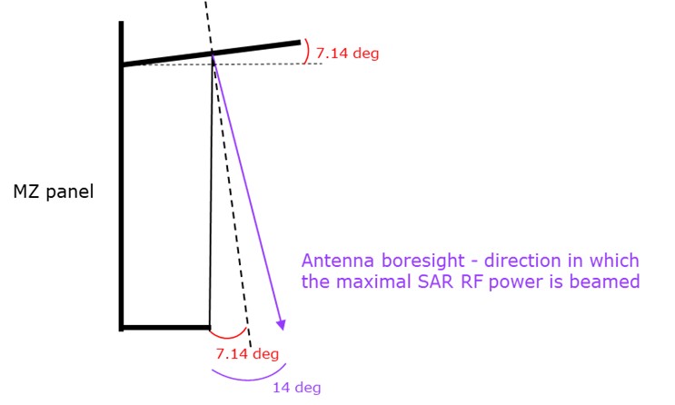
SAR boresight |
The SAR boresight is the direction in which the maximal SAR RF power is beamed (see explanatory figure below.
|
||||||||||||||||||||
|
Look angle |
The look angle is the angle between the spacecraft nadir direction and the antenna boresight. |
||||||||||||||||||||
|
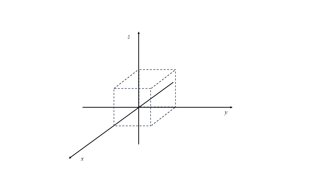
Positive Roll Angle observation |
To reach a given incidence angle over a given area can be achieved in two directions (right or left looking), requiring a positive or negative roll of the Spacecraft (rotation around its Y axis).
Note that due to the natural tilt of the reflectarray in the positive roll direction, the PRA requires a smaller attitude change from the SC than an NRA for a given incidence angle. |
||||||||||||||||||||
|
Negative Roll Angle observation |
See Positive Roll Angle description |
||||||||||||||||||||
| VenSAR antenna pointing angle |
The antenna electrical boresight relative to nadir, and thus doesn’t depend on any particular target. The SAR boresight is the direction in which the maximal SAR RF power is beamed. |
||||||||||||||||||||
|
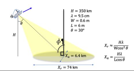
VenSAR target/local incidence angle (Φ) |
The target (or local) incidence angle is the angle Φ between the normal to the local plane on the planet's surface and the direction of the incident radiation.
|
||||||||||||||||||||
|
VenSAR look angle (ɵ) |
Instrument look angle ɵ (or also called view geometry or view angle), i.e. angle between nadir and the surface target line-of-sight at the centre of the radar footprint.
|
||||||||||||||||||||
|
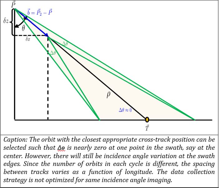
VenSAR look angle (ɵ) variation across-track |
 |
||||||||||||||||||||
|
VenSAR off-nadir viewing geometry or view angle (ɵ) |
Angle between nadir and the target line-of-sight at the centre of the radar footprint (ɵ). It is identical to the VenSAR look angle.
|
||||||||||||||||||||
|
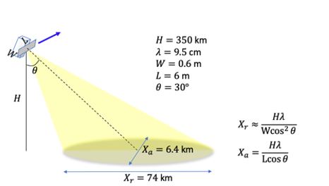
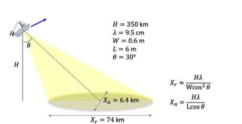
VenSAR resolution |
See appendix D in the EnVision Science Requirements Document (SciRD). |
||||||||||||||||||||
Reference Frames
Reference frames are defined in a specific document : ESA-ENVIS-EST-MIS-RS-008 Definition
of reference frames and pointing angle errors.