AOCS - Ulysses
Attitude and Orbit Control Subsystem
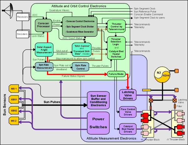
This diagram shows the connectivity between units in the AOCS. Click on an area of this image to obtain a more detailed view of the units of interest.
The Attitude and Orbit Control Electronics uses inputs from the spacecraft receivers, decoders, Sun Sensors, and ground commands to control the spacecraft spin rate, attitude, and manoeuvres. It has four main modes of operation: spin control, Solar Aspect angle control, Earth pointing attitude control using 'conscan', and thruster control by telecommand.
The Attitude Measurement Electronics processes raw Sun pulses from the Sun Sensors, and provides most of the power switching for the AOCS. This unit also controls power to the valves in the Reaction Control Subsystem and to the heaters used to heat the thrusters before firing.
The Reaction Control Subsystem consists of the tank, pipes, valves and thrusters that contain and regulate the flow of hydrazine rocket fuel from the spacecraft. Eight thrusters in two blocks of four (Thruster Block 1 and Thruster Block 2) are used to change the spacecraft trajectory and the direction in which it points.
Four multiple slit Sun Sensors provide pulses whenever the sun crosses their field of view during the 12 second spin cycle. These pulses are processed to provide an unambiguous Spin Reference Pulse (SRP) that defines the start of a spin cycle and allows it to be divided up into sectors. This provides the basis for measuring the direction of origin of many experiment events, as well as giving a datum from which to time thruster firings. The sun sensors also provide the Solar Aspect Angle (SAA), the angle between the spin axis and the spacecraft-Sun vector.
AOCS Operations
Because Ulysses spins at 5 rpm and is not in the presence of large perturbing forces, it maintains a stable inertial attitude for long periods of time. The critical attitude control requirement for Ulysses is to keep the HGA boresight pointed at the Earth to within about 0.5°. The precise magnitude of the offpointing depends on the link budget for a given mission phase.
The AOCS has two closed loop control modes that can control the SAA. 'SAA Control' mode slews the spacecraft so that the SAA comes inside a deadband that can be defined by telecommand. 'Constant SAA Slew' mode enables the spacecraft spin axis to describe a cone around the spacecraft-Sun line at an approximately constant SAA; both these modes were provided in order to assist in performing initial Earth acquisition in the early mission, and Earth reacquisition manoeuvres in case Earth pointing was lost later in the mission.
The AOCS also has a single closed loop control mode that can control spin rate from the SRP should large spin disturbances be encountered. Such disturbances have only been experienced during Trajectory Correction Manoeuvres (TCMs) where the effects of small thruster misalignments and impulse mismatches is magnified because of the long burn times necessary to complete such manoeuvres.
The angle between the spacecraft spin axis and the Earth is measured by the AOCS conical scanning system (Conscan). The High Gain Antenna (HGA) boresight is mounted with a small offset from the spin axis, so that as the spacecraft rotates the uplink signal strength appears to vary sinusoidally. The amplitude and phase of this signal can be used to derive the magnitude and direction of the Earth offpointing. The Conscan system can also operate in a closed-loop mode, where Earth offpointing phase and magnitude information is used to time axial thruster firings such that the offpointing is kept at acceptably low levels.
Thrusters can also be controlled by telecommand; thruster firing phase, on-time, and number of pulses can be calculated on the ground and loaded directly to the AOCS. All AOCS thruster control modes are protected against failure by spin, SAA, and Conscan failure deadbands, which if transgressed cause latching valve closure and termination of the manoeuvre.
The spacecraft has four spin thrusters (mounted to give a tangential thrust in the spin plane) and four axial thrusters (mounted to give axial thrust in the +Z and -Z direction) mounted in two thruster blocks (Block 1 & Block 2). Routine attitude manoeuvres consist of pulsing an axial thruster at the correct phase in the spin cycle to slew the spin axis across the Earth path.








 Sign in
 Science & Technology
