Technical Details - EPIC - XMM-Newton
The European Photon Imaging Camera (EPIC) onboard XMM-Newton
|
|
This description is mostly based on the information contained in the papers
Strüder, L. et al. 2001, A&A 365, L18, and Additional information can be obtained from the XMM-Newton Users' Handbook. |

Contents:
1. Introduction
2. Chip Geometry
2.1. MOS CCDs
2.2. pn CCDs
3. The Camera Concept
3.1. The basic principle of the MOS CCDs
3.2. The basic principle of the pn-CCDs
4. Operating Modes
5. Instrument Characteristics
5.1. Quantum Efficiency
5.1.1. EPIC MOS
5.1.2. EPIC pn
5.2. Background
6. Filters and Effective Area
7. EPIC Radiation Monitor
1. Introduction
The XMM-Newton spacecraft is carrying a set of three X-ray CCD cameras, comprising the European Photon Imaging Camera (EPIC). Two of the cameras are MOS (Metal Oxide Semi-conductor) CCD arrays (referred to as the MOS cameras). They are installed behind the X-ray telescopes that are equipped with the gratings of the Reflection Grating Spectrometers (RGS). The gratings divert about half of the telescope incident flux towards the RGS detectors such that (taking structural obscuration into account) about 44% of the original incoming flux reaches the MOS cameras. The third X-ray telescope has an unobstructed beam; the EPIC instrument at the focus of this telescope uses pn CCDs and is referred to as the pn camera.
The EPIC cameras offer the possibility to perform extremely sensitive imaging observations over the telescope's field of view (FOV) of 30 arcmin and in the energy range from 0.15 to 15 keV with moderate spectral (E/Delta E ~ 20-50) and angular resolution (PSF, 6 arcsec FWHM).
All EPIC CCDs operate in photon counting mode with a fixed, mode dependent frame read-out frequency, producing event lists, i.e. tables with one entry line per received event, listing (among others) attributes of the events such as the position at which they were registered, their arrival time and their energies. The two types of EPIC, however, differ in some major aspects. This does not only hold for the geometry of the CCD arrays and the instrument design but also for other properties, like e.g., their readout times.
Another experiment on board of XMM-Newton is the EPIC Radiation Monitor (ERM). The main function of the ERM is the detection of the radiative belts and solar flares in order to supply particle environment information for the correct operation of the EPIC camera. In addition, the ERM provides detailed monitoring of the space radiative environment constituting a reference for the development of detectors to be used in futures missions.
2. Chip Geometry
2.1. MOS CCDs
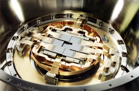 The CCDs of one of the MOS cameras in the cryostat. |
There are seven EEV type 22 front-illuminated CCDs in the focal plane of each MOS camera. The central CCD is at the focal point on the optical axis of the telescope while the outer six are stepped towards the mirror by 4.5 mm to follow approximately the focal plane curvature, and improve the focus for off-axis sources. The CCDs are buttable with a dead region of less than 300 microns wide on three sides; to minimise the dead space, adjacent CCDs are stepped by about 1 mm to overlap by 300 microns. The imaging area is ~2.5 x 2.5 cm, so that a mosaic of seven covers the focal plane 62 mm in diameter, equivalent to 28.4 arcmin. The imaging section has 600 x 600, 40 micron square, pixels; one pixel covers 1.1 x 1.1 arcsec on the FOV; 15 pixels cover the mirror PSF half energy width of 15 arcsec. The readout register is split into two sections, ending in a readout node. The full CCD image can be read out using either node, or read out using both nodes simultaneously, to halve the readout time. The two MOS cameras are arranged on the spacecraft focal plane bulkhead so that the CCDs are orthogonal. This means that the 300 micron gaps between the outer CCDs in one camera are covered by their opposite numbers in the other camera. |
2.2. pn CCDs
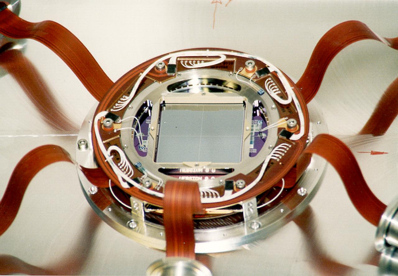
The CCDs of the pn camera: The picture shows the twelve chips mounted and the connections to the integrated preamplifiers. |
In case of the pn camera, the spatially uniform detector quality over the entire FOV is realized by the monolithic fabrication of twelve 3 x 1 cm pn-CCDs on a single wafer. The four individual quadrants each having three pn-CCD subunits with a format 200 x 64 pixels are operated in parallel. This division of the focal plane in subunits was made because of redundancy reasons. The pn array was especially designed for the XMM-Newton X-ray telescope FOV and mirror PSF having an imaging area of 6 x 6 cm (covering about 97% of the FOV; about 6 cm2 of the CCD's sensitive area are outside the FOV and is used for background studies) and a pixel size of 150 x 150 microns (4.1 arcsec) with a position resolution of 120 microns, resulting in an equivalent angular resolving capability for a single photon of 3.3 arcsec. An overview of the internal boundaries of the pn-CCD focal plane is available here. The focal point of the X-ray telescope is in CCD0, quadrant 1. |
3. The Camera Concept
3.1. The basic principle of the MOS CCDs
The MOS EEV CCD22 is a three-phase frame transfer device on high resistivity epitaxial silicon with an open-electrode structure; it has a useful quantum efficiency in the energy range 0.2 to 10 keV. The low energy response of the conventional front illuminated CCD is poor below ~700 eV because of absorption in the electrode structure. For EPIC MOS, one of the three electrodes has been enlarged to occupy a greater fraction of each pixel, and holes have been etched through this enlarged electrode to the gate oxide. This gives an "open" fraction of the total pixel area of 40%; this region has a high transmission for very soft X-rays that would have otherwise be absorbed in the electrodes. In the etched areas, the surface potential is pinned to the substrate potential by means of "pinning implant". High energy efficiency is defined by the resistivity of the epitaxial silicon (around 400 Ohm-cm). The epitaxial layer is 80 microns thick (p-type). The actual mean depletion of the flight CCDs is between 35 to 40 microns: the open phase region is not fully depleted.
3.2.The basic principle of the pn-CCDs
The schematic view looking into the pn-CCD introduces intuitively the advantages of the concept: X-rays hit the detector from the rear side. In the event of an X-ray interaction with the silicon atoms, electrons and holes are generated in numbers proportional to the energy of the incident photon. The average energy required to form an electron-hole pair is 3.7 eV at -90° C. The strong electric fields in the pn-CCD detector separate the electrons and holes before they recombine. Signal charges (in our case electrons), are drifted to the potential minimum and stored under the transfer registers. The positively charged holes move to the negatively biased back side, where they are 'absorbed'. The electrons, captured in the potential wells 10 microns below the surface can be transferred towards the readout nodes upon command, conserving the local charge distribution patterns from the ionization process. Each CCD line is terminated by a readout amplifier.
4. Operating Modes
The EPIC cameras allow several modes of data acquisition. Note that in the case of MOS the outer ring of 6 CCDs remain in standard full-frame imaging mode while the central MOS CCD can be operated separately. The pn camera CCDs can be operated in common modes in all quadrants for full frame, extended full frame and large window mode, or just with one single CCD (CCD0 in quadrant 1 = CCD4 according to SAS numbering conventions) for small window, timing and burst mode.
- full frame and extended full frame (pn only)
- In this mode, all pixels of all CCDs are read out and thus the full FoV is covered
- partial window
- a) MOS
In a partial window mode the central CCD of both MOS cameras can be operated in a different mode of science data acquisition, reading out only part of the CCD chip: in small window mode an area of 100 x 100 pixels is read out, whereas in large window mode an area of 300 x 300 pixels is active.
b) pn
In large window mode only half the area of all 12 CCDs is read out, whereas in small window mode only the part of CCD0 in quadrant 1 (CCD4 according to SAS numbering conventions) at the focal point is used to collect data - timing
- a) MOS + pn
In timing mode, imaging is made only in one dimension, along the column axis. Along the row direction, data from a predefined area on one CCD chip are collapsed into a one-dimensional row to be read out at high speed
b) pn only
A special flavour of the timing mode of the EPIC pn camera is the burst mode, which offers very high time resolution, but has a low duty cycle of 3%
Further details about the EPIC science modes are given in the XMM-Newton Users' Handbook.
5. Instrument Characteristics
5.1. Quantum Efficiency
One of the factors to be taken into account when determining the effective area of the EPIC cameras is their quantum efficiency.
It is the quantum efficiency of the EPIC-MOS chips that limits the energy passband at its high energy end, while the pn camera can detect photons with high efficiency up to 15 keV.
5.1.1. EPIC MOS:
The quantum efficiency of the MOS CCDs varies a little from CCD to CCD at very low energies. It is a smooth function except near the edges of silicon and oxygen: the carbon and aluminum edges are apparent in the thin and medium filter responses, tin appears as well in the thick filter (a description of the filters is given below, the gold edges of the mirror are apparent in the overall quantum efficiency). The response near these edges was measured using different beams at the Orsay synchrotron. The measurements have been linked together using celestial sources.
5.1.2. EPIC pn:
The fully depleted 280 µm of silicon determines the pn detector efficiency on the high energy end, while the quality of the radiation entrance window is responsible for the low energy response. The absolute quantum efficiency calibration was performed at PTB (BESSY synchrotron in Berlin) and the Orsay synchrotron. The drop of quantum efficiency at the lowest energies is caused by the properties of the silicon L-edge. The drop of about 5% of quantum efficiency at 528 eV is due to the additional absorption in the SiO2 passivation on the detector surface. The other prominent feature is the typical X-ray absorption fine structure (XAFS) behavior around the silicon K-edge at 1.838 keV, enlarged in the inset. At higher energies the solid line nicely fits the photon absorption data for 300 µm of silicon. The solid line is a fit to the measured data with a depletion thickness of 298 µm. The quantum efficiency is not expected to change during the XMM-Newton lifetime under nominal conditions.
5.2. Background
The EPIC background can be divided into two parts: a cosmic X-ray background (CXB), and an instrumental background. The latter component may be further divided into a detector noise component, which becomes important at low energies (below 200 eV) and a second component which is due to the interaction of particles with the structure surrounding the detectors and the detectors themselves. This component is characterized by a flat spectrum and is particularly important at high energies (above a few keV). The particle induced background can be divided into two components: an external 'flaring' component, characterized by strong and rapid variability, which is often totally absent and a second more stable internal component. The flaring component is currently attributed to soft protons (with energies smaller than a few 100 keV), which are funneled towards the detectors by the X-ray mirrors. The stable component is due to the interaction of high energy particles (with energies larger than some 100 MeV) with the structure surrounding the detectors and possibly the detectors themselves.
Further details about the origin of the EPIC background are given in the document XMM-SOC-CAL-TN-0016. The many diverse aspects of the XMM-Newton radiation environment were discussed extensively at a Workshop held at the XMM-Newton SOC in December 2000. More details on the instrumental background are given in the XMM-Newton Users' Handbook.
6. Filters and Effective Area
As the EPIC detectors are not only sensitive to X-ray photons but also to IR, visible and UV light, the cameras include aluminised optical blocking filters to reduce the contamination of the X-ray signal by those photons.
If such photons are registered by the EPIC detectors, the data analysis would be impeded in three ways:
- Shot noise on the optically generated photo-electrons will increase the overall system noise
- The energy scale will be incorrectly registered, because a nominally zero signal will have a finite offset. For each optically generated photo electron, the energy scale shifts by about 3.6 eV.
- Optically-generated photo electrons can lead to a saturation of electron traps, changing (improving) the charge transfer inefficiency.
There are four filters in each EPIC camera. Two are thin filters made of 1600 Å of poly-imide film with 400 Å of aluminium evaporated on to one side; one is the medium filter made of the same material but with 800 Å of aluminium deposited on it; and one is the thick filter. This is made of 3300 Å thick Polypropylene with 1100 Å of aluminium and 450 Å of tin evaporated on the film. The filters are self-supporting and 76 mm in diameter. The remaining two positions on the filter wheel are occupied by the closed (1.05 mm of aluminium) and open positions, respectively. The former is used to protect the CCDs from soft protons in orbit, while the open position could in principle be used for observations where the light flux is very low, and no filter is needed.
The EPIC MOS effective area for each of the optical blocking filters and without a filter
The EPIC pn effective area for each of the optical blocking filters and without a filter
Combined effective area of all telescopes assuming that the EPIC cameras operate with the same filters, either thin, medium or thick
7. EPIC Radiation Monitor
The EPIC Radiation Monitor (ERM) experiment is a part of EPIC. The ERM has a function of detection of radiation belts and solar flares in order to supply particle environment information for the correct operation of the EPIC camera. Moreover, the ERM is used for the detail monitoring of the space radiative environment, constituting a reference for the development of detectors to be used in future missions. A technological experiment is also included in the ERM: Evalcomp. The purpose of this experiment is to evaluate the susceptibility to single event upsets (SEU) of various type of memories.
Three parts constitute the ERM experiment:
- The detection head, ERMD, equipped with its thermal cover.
- The electronics for the data handling and interfacing with the spacecraft bus, ERME, which includes Evalcomp for SEU counting with particles spectra correlation.
- The harness between ERMD and ERME called ERHA and ERHB.
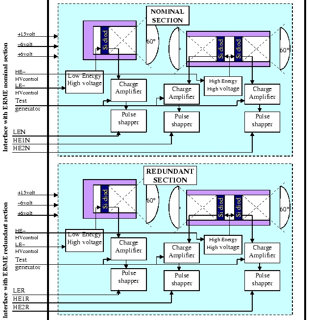
7.1 ERM detectors
The ERM contains two types of silicon diode detectors, one for low energy and one for high energy, fully redundant, and assembled on a single mechanical structure as the electronic box:
a) Low Energy detector characteristics:
A Silicon detector, 500 mm of thickness, 0.85 cm2 of surface with one programmable low threshold from 0 to 256 keV.
It registers events in the energy range from 50 keV to 5 MeV. Dynamic range of the preamplifier from 40 keV to 5 MeV with a conversion factor of 4 MeV/3 V. The range is digitised in the range from 0 to 3 V full scale with a resolution of 256 channels.
The maximum counting rate for electrons is 106 e-/s and for the protons 2 x 10⁴ p+/s.
b) High Energy detector characteristics:
Two silicon detectors, 500 mm of thickness, 0,85 cm2 of surface with one programmable low threshold from 0 to 512 keV.
It registers events in the energy range from 500 keV to 12 MeV. Dynamic range of the preamplifier from 130 keV to 12 MeV with a conversion factor of 8 MeV/3 V. The range is digitised from 0 to 4.4 V full scale with resolution of 256 channels.
The maximum counting rate is less or equal 5 x 10⁵ count per second. After sum of the pulses, the resulting count rate is 106 count per second, 10% of which are in coincidence.
The block diagram given here after shows the ERMD functions:
7.2 The ERM signal "Warning Flag"
This signal is an alert signal for EPIC and will be delivered to the telemetry every 4 second, by the ERM. This signal is the results of computation done on the detector counters and is used as a trigger to close the EPIC cameras protecting them during high radiation intervals, e.g. in the Earth's radiation belts or during solar flares.
The computing method is the following: each counting rate is compared to a 16 bit reference word, set by telecommand. Each 4 sec, if at least one of the detector rates is greater than its reference word, then a counter will be incremented by one unit and, if not, the counter will be reset. When the content of this counter is equal to a commendable value N, i.e. when the condition "at least one counting rate is higher than its reference for 4 sec" is met N successive times, then the signal "Warning Flag" will be generated, until a command, sent from the ground, reset the "Warning Flag", or when complementary conditions occurs. This flag is set if N successive times one of the detector counting is found greater than his associated threshold. The flag is cleared if N successive times the detector counting are less than their associated threshold or if the Warning Flag reset telecommand is received.
- The MOS camera system was produced by a consortium which includes Leicester University (CCDs and camera head), the University of Birmingham (thermal control system) and CEA Service d'Astrophysique Saclay (control and event recognition electronics).
- The pn CCD array was fabricated in the MPI-semiconductor laboratory, the pn camera was built by MPI für extraterrestrische Physik and Astronomisches Institut Tübingen.
- The EPIC Radiation Monitor was developed by CESR Toulouse.
Back to the technical descriptions index.