Filter Wheel - XMM-Newton
Filter wheel
In each detector there is a filter wheel. The filter wheel has 11 apertures, one of which is blanked off to serve as a shutter, preventing light from reaching the detector. Another seven filter locations house lenticular filters, six of which constitute a set of broad band filters for colour discrimination in the UV (UVW1, UVM2, UVW2) and optical (U, B, V) between 180 nm and 580 nm. The seventh is a "white light" filter which transmits light over the full range of the detector to give maximum sensitivity to point sources. The remaining filter positions contain two grisms, one optimized for the UV and the other for the optical range, and a x4 field expander (or Magnifier; currently not operational) to provide high spatial resolution in a 380-650 nm band of the central portion of the field of view.
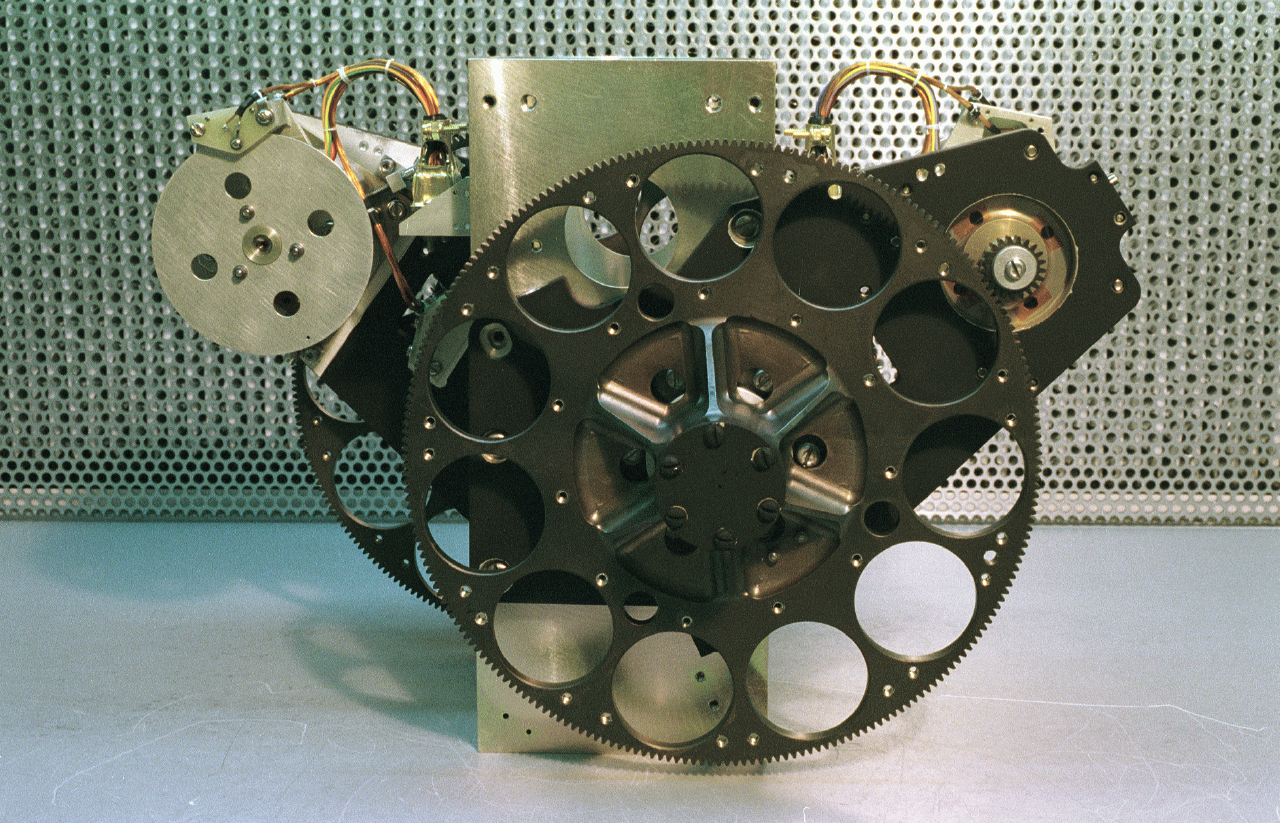
OM blue detector with filter wheel
The filter wheel is powered by stepper motor, which drives the wheel in one direction only. The filters are arranged taking into account the need to distribute the more massive elements (grisms, Magnifier) uniformly across the wheel. The wheel is driven by a pinion on a 4-phase stepper motor shaft, with a gear ratio of 11 to 1. Thus one revolution of the motor, which requires 200 steps, moves the wheel from one optical element to another and 2200 steps completely rotate the filter wheel. The wheel position will normally be determined in open loop mode by step counting from a known datum position.
Coarse and fine positions sensors are provided to relocate the datum position should it be lost, verify the wheel position during and after every rotation and to confirm that the centre of any optical element has been found, although the element is not identified. The reflective infra-red coarse position sensor is fitted to the wheel and gives a true output when the wheel is within about ± 15° of the datum position. The infra-red fine position sensor, which is used in transmissive mode, is fitted to the rear end of the motor. An occulting disk with a small aperture, through which the sensor looks, is fitted to the rear extension of the motor shaft. It is aligned such that an element will be correctly positioned when the fine sensor gives a true reading and the first phase is energized. Thus it is only at the datum position that both the coarse and fine sensors give a true output.
Photo courtesy of Mullard Space Science Laboratory, UK.








































 Sign in
 Science & Technology